

 Completed
Leaf-free Fan Desk Lamp
PRO Leaf-free Fan Desk Lamp
License
:Public Domain
Description
Chapter 1 Bladeless Fan Table Lamp Finished Product Display and Use Instructions
Fans and desk lamps are very commonly used household appliances, and the two-in-one products of fans and table lamps on the market are still relatively rare, basically just a simple splicing of the two, and the performance and power are also difficult to guarantee. Combined with the existing problems and personal DIY hobbies, it was decided to make a delicate all-open-source bladeless fan table lamp. The following is the display of the finished product and the instructions for use.
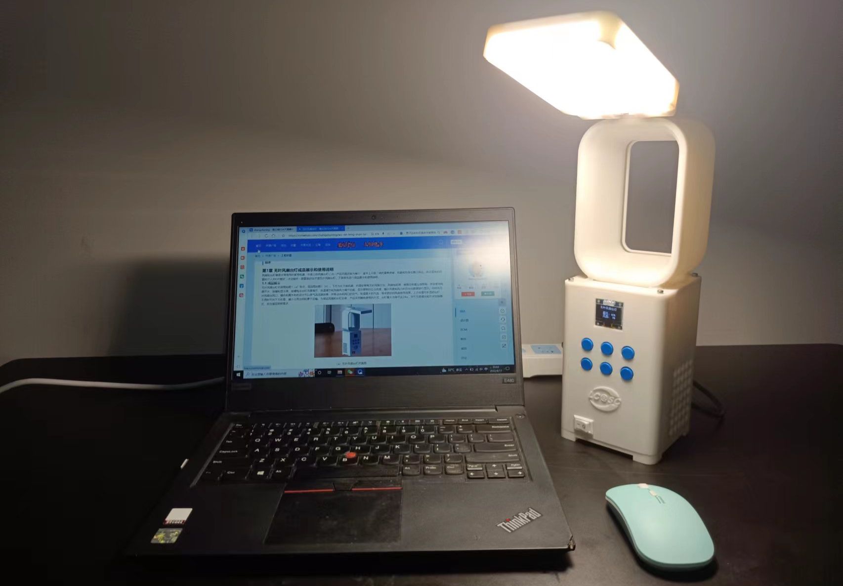
1.1 Finished product display
The simulation diagram of the bladeless fan table lamp is shown in Fig.1 (a), and the finished product is shown in Fig.1 (b). The bottom is a rectangular chassis, which is equipped with a bladeless fan main control, fan motor, etc., printed with the JLC icon on the surface, and installed with a power switch, buttons and a display screen, the buttons include the brightness adjustment of the desk lamp, the color temperature adjustment and the fan wind adjustment function, and the display screen displays the percentage data of positive white brightness, warm white brightness and wind power. The middle is the bladeless fan outlet, which is designed to multiply the airflow rate and drive the air in the middle to form a larger airflow and bring better fan use effect. A foldable table lamp is placed on the top and can be folded down when not in use, reducing the footprint and making it easy to transport. In order to ensure the power of the fan and the lamp, the product adopts the mode of plug-in use, the maximum power of the lamp can reach 24W, and the stepless dimming and switch mode can fully meet the lighting needs.

(a)Simulation diagram of bladeless fan table lamp

(b)Physical drawing of bladeless fan table
Fig.1 Finished bladeless fan table lamp
1.2 Instructions for Use
The use of this bladeless fan table lamp is very simple, mainly as follows:
(1)Plug the double-ended socket cable into the chassis first, and then plug it in;
(2)Through the power switch on the chassis, it can be turned on and off;
(3)After starting, the bladeless fan lamp can be controlled by six buttons, the button function is divided into long press and short press, short press can be adjusted according to the gear, long press can be stepless control, the function of each button is shown in Fig. 2;
(4)The desk lamp module has the function of switching the mode of switching, which can be turned on quickly after turning off the power switch, and the lighting mode can be switched, and the four modes are full bright, white, warm white, and night light.

Fig.2 Schematic diagram of key functions
In addition, the bladeless fan lamp also has a built-in HC08 Bluetooth module, which can be controlled through the mobile APP, and the specific operation process is as follows:
(1) Download the "HC Bluetooth Assistant" APP on your mobile phone;
(2) Turn on the bladeless fan and connect to the Bluetooth of the bladeless fan desk lamp through the HC Bluetooth assistant;
(3) Edit the button content of the Bluetooth APP, and the button content and control function correspond as shown in Table 1;
Table 1 Comparison table of key content functions
|
Table 1 Comparison table of key content functions |
Function |
|
#Set10012X. |
Brightness increases |
|
#Set10013X. |
Brightness decreases |
|
#Set10014X. |
The color temperature increases |
|
#Set10015X. |
Color temperature is reduced |
|
#Set10016X. |
Nightlight |
|
#Set10017X. |
Fans increased |
|
#Set10018X. |
Fans are reduced |
|
#Set10011X. |
Print the switch |
|
#Ask0. |
Query information |
(4) After editing the content of the buttons, you can control the buttons via Bluetooth.
Chapter 2 3D Form Factor Design
The design of electronic products mainly includes three parts: 3D shape design, hardware design and software design, which reflect the relationship between mutual constraints and mutual support. When designing this bladeless fan table lamp product, I first carried out product positioning, and I positioned it as a desktop small bladeless fan with increased power desk lamp.
Good appearance was an important factor in attracting users, and the final choice was made for the rectangular folding shape concept, and then the Catia software was used to design the specific 3D shape. The 3D model and exploded view of this bladeless fan lamp are shown in Figs. 3(a) and 3(b), respectively.
The 3D structure printing parts mainly include the following parts: base, box shell, fan airway shell, fan turbine fan blade, air outlet shell, table lamp shell, etc.
 (a) 3D model of a bladeless fan table lamp

(b) Exploded view of the bladeless fan table lamp
Fig.3 3D model
Chapter 3 Hardware Design
The hardware circuit of the bladeless fan table lamp contains a total of 3 circuit boards, which are the main control board, the button board and the lamp board of the bladeless fan table lamp. The PCB file is designed using the open source software of Richtron EDA Professional Edition, and the schematic diagram and PCB of the three circuit boards are introduced and explained below.
3.1 Master control board schematic and PCB design
The main control board circuit includes three parts: control circuit, lamp drive circuit and fan drive circuit.
The schematic diagram of the control circuit is shown in Fig.4, which mainly includes chip peripheral circuit, display interface circuit, Bluetooth interface circuit, button interface circuit and serial port debugging circuit. The control core adopts the commonly used STM32F103C8T6 chip, which can also be replaced by the domestic HK32 F103C8T6 chip.

Fig.4 Schematic diagram of the control circuit
The schematic diagram of the desk lamp circuit is shown in Fig.5, which mainly includes a rectifier circuit, two LED driver circuits and a 220V AC to 3.3V DC circuit. The core components of the rectifier circuit are 4 diodes, which also contain filter capacitors, and a 50HZ pulse signal is drawn through the resistor and capacitance parts, and the control chip can quickly switch the function of switching the lighting mode by detecting the pulse. The core device of the LED driver is the BP2596 chip, the core device that generates 3.3V DC is the BP2525 chip, and the 3.3V is used for the power supply of the control circuit.

Fig.5 Schematic diagram of desk lamp circuit
The schematic diagram of the fan circuit is shown in Fig.6, a 12V DC power supply is generated through the step-down module to supply power to the brushless motor, the maximum output power can reach 20W, the brushless motor is connected to the ESC, and the PWM signal is used for control.

Fig.6 Schematic diagram of the fan circuit
The simulation diagram and the physical diagram of the PCB of the main control board are shown in Fig. 7 (a) and Fig.7 (b) respectively, the left side of the control board is the fan circuit, the upper right side is the LED drive circuit, and the lower right side is the control circuit

(a) PCB simulation drawing

(b) PCB physical drawing
Fig.7 PCB diagram of the main control board
3.2 Schematic diagram and PCB design of the button board
The key board circuit is very simple, the schematic diagram is shown in Fig.8, the circuit board simulation diagram is shown in Fig. 9(a), and the physical circuit board diagram is shown in Fig.9(b).

Fig.8 Schematic diagram of key circuit

(a) PCB simulation drawing

(b) PCB physical drawing
Fig. 9 PCB diagram of the button board
3.3 Schematic diagram and PCB design of the lamp board
The circuit of the lamp board is designed with 24 1W LED lamp beads, of which 12 are positive white, 12 are warm white, and the voltage of each one is 6V. The schematic diagram is shown in Fig.10, the circuit board simulation diagram is shown in Fig.11(a), and the physical circuit board diagram is shown in Fig.11(b). When designing the PCB of the light board, the pure white and warm white LEDs should be evenly arranged, and the ink color should be white.

Fig.10 Schematic diagram of the lamp board circuit

(a) PCB simulation drawing

(b) PCB physical drawing
Fig.11. PCB diagram of the lamp board
Chapter 4 Software Design
4.1 Software code structure analysis
The software first uses STM32Cube to generate configurations, including pin configuration, clock configuration, download configuration, serial port configuration, etc. (please refer to the source code for details). Then use Keil5 to develop on the generated code, add folders and files, and the final code structure is shown in Fig.12, and the added folders include "APP" and "APP_Function". The "APP" folder is the function of the upper application layer, and contains a simple task system designed by itself, which is called in the main function; The "APP_Function" folder contains the encapsulation of the serial port, system Flash read/write, and low-level functions related to the display, which are called by the application layer functions. The main.c file contains a detailed description of the code structure, and multiple tasks are executed in real time through the task system, as shown in Fig.12.

Fig.12 . Software structure analysis diagram
4.2 Detailed explanation of software files
Table 2 shows the C files and their corresponding functions in the software code: in addition to the three C files contained in the "APP" folder, the All_Data, All_Task, App_Function, and All_Data files contain parameter initialization functions, which can be used to store the basic information of some devices and save the parameters when power is off. The basic functions for building the task system are included in the All_Task file, and the porting method is detailed in its h file, which is an original task system that can be generalized, as shown in Fig.2. App_Function file contains the topmost functions of each task function.
Table 2 Comparison table of key content functions
|
filename |
function |
|
All_Data.c |
It contains a system parameter structure and integrates all data into a machine data structure object based on object-oriented programming ideas |
|
All_Task.c |
The original simple task system, which contains the basic functions for building a task system, and the porting method is detailed in its h file |
|
App_Function.c |
The top-level function that contains each task function is called in the task system |
|
Uart_Comunicate_Profile.c |
Serial communication protocol file, used to send and receive Bluetooth commands and system debugging |
|
Uart.c |
The underlying function of the serial port |
|
Uart1.c |
Serial port 1 application layer function |
|
System.c |
It is used to store the basic information of some devices and save the parameters when the power is off, and the parameters are stored in the chip Flash |
|
OLED_I2C.c |
The display communication controls the underlying functions |
Chapter 5 Precautions
The bladeless fan table lamp product is a plug-in electrical appliance, there is a high voltage on the circuit board after power-on, do not directly touch the circuit board with your hands in the power-on state during the production and debugging process.
The whole production process is as follows:
(1) Prepare the 3D printing of the shell, the "stl" folder in the data includes all the required prints, which can be printed through the Lichuang 3D printing service;
(2) Circuit board making and material preparation, including a total of three circuit boards, in addition to the circuit board supporting components, also need to prepare a boat-shaped switch, a double-ended power socket socket, a power cord, hot melt adhesive, a number of 3mm diameter screws, brushless motor and ESC;
(3) Circuit board soldering, code downloading, fan lamp test;
(4) Assemble the whole machine (the printing support at the air outlet needs to be cleared, the power cord of the desk lamp needs to pass through the middle of the fan air outlet, and the lower inlet of the fan cylinder and the upper outlet of the table lamp connector need to be sealed with hot melt adhesive).
Chapter 6 Video Attachments and Links to Material Attachments
6.1 Video Attachment Links
Video link of bladeless fan table lamp station B (welcome to cheer):
[Practice for two and a half years bladeless fan table lamp design - Bilibili] https://b23.tv/4I4MGDr
[Practice for two and a half years bladeless fan table lamp assembly - Bilibili] https://b23.tv/leIjMhR
[Bladeless fan table lamp display with a practice duration of two and a half years - Bilibili] https://b23.tv/lLbxHfc
6.2 Links to Attachments
The information of the bladeless fan table lamp contains instruction documents, 3D printing materials, hardware information and software information, and the download link of the information of Lichuang Open Source Plaza is: https://oshwhub.com/zhangshuning/wu-xie-feng-shan-tai-deng.
Chapter 7 Acknowledgments
Thanks to JLC's PCB open source design software, compared with AD, it is more convenient to use and meets the actual production needs. Thanks to the open source activities of the JLC Spark Program, the material costs in the product development process were reimbursed.
Designed by zhangshuning (from OSHWHub)
Link:https://oshwhub.com/zhangshuning/wu-xie-feng-shan-tai-deng
Design Drawing
 Empty
Empty
Comment